
After seeing mini radar project by Aron Horan last year (http://robohoran.wordpress.com/2013/11/27/mini-radar/), I decided to give it a go using a webcam and a laser. The reason for doing this is because using an ultrasonic sensor does not provide precise readings of gaps due to its large viewing angle, the Sharp IR sensor is another option but it produces a noisy output. This can be filtered out in code, but it still does not offer the precision and range needed for doing something like making a 2d map of a room. Part two of this project is spinning the webcam and laser and mapping a room, maybe eventually mounting it on a robot. There is a fair amount of information on webcam rangefinders on available online, most of it is fairly similar due to plagerisation and all that craic. The source I found most useful was a blog by Todd Danko https://sites.google.com/site/todddanko/home/webcam_laser_ranger.
Step 1: Get a webcam, get a laser , fix the webcam in place but leave the laser alone for now
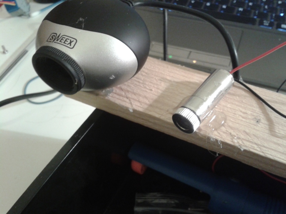
Webcam and laser hot glued to a piece of wood
Calculating distance using this method works off basic trigonometry:
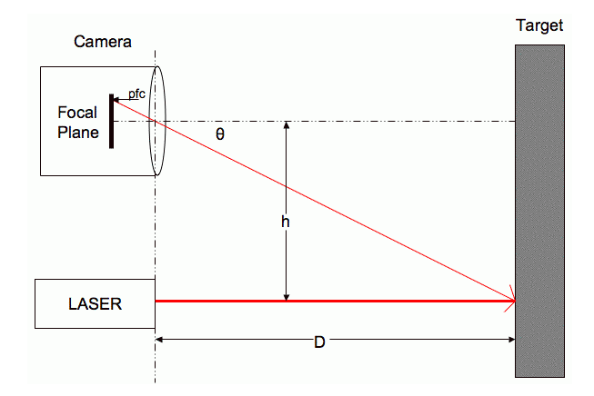
Webcam and laser trigonometry
Source of image and equations : https://sites.google.com/site/todddanko/home/webcam_laser_ranger
Step 2: grabbing images from the webcam and doing stuff with them
From the top equation we know that the distance to the object equals the distance between the webcam and laser , divided by the tan of theta. The next step is to work out how theta relates to the pixels contained in the webcam image. To work out theta we need to find the radians per pixel pitch of the webcam and the radian offset. These are constants for a particular webcam, the pixels from focal plane will change depending on how far away the image is. ( pixels from focal plane just means how many pixels the laser is from the centre of the image ). The OpenCV library for python was used to get images from the webcam and process them. Here is the code:
## program written by Shane Ormonde 7th sept 2013
## updated on 25th January 2014
## calculates the distance of a red dot in the field of view of the webcam.

import cv2
from numpy import *
import math

#variables
loop = 1
dot_dist = 0

cv2.namedWindow("preview")
vc = cv2.VideoCapture(1)

if vc.isOpened(): # try to get the first frame
    rval, frame = vc.read()

else:
    rval = False
    #print "failed to open webcam"

if rval == 1 :

	while loop == 1:
			cv2.imshow("preview", frame)
			rval, frame = vc.read()
			key = cv2.waitKey(20)
			if key == 27: # exit on ESC
				loop = 0
			num = (frame[...,...,2] > 236)
			xy_val =  num.nonzero()

			y_val = median(xy_val[0])
			x_val = median(xy_val[1])

			#dist = ((x_val - 320)**2 + (y_val - 240)**2 )**0.5 # distance of dot from center pixel
			dist = abs(x_val - 320) # distance of dot from center x_axis only

			print " dist from center pixel is " + str(dist)

			# work out distance using D = h/tan(theta)

			theta =0.0011450*dist + 0.0154
			tan_theta = math.tan(theta)

			if tan_theta > 0: # bit of error checking
				obj_dist =  int(5.33 / tan_theta)

			print "\033[12;0H" + "the dot is " + str(obj_dist) + "cm  away"
elif rval == 0:
		print " webcam error "
Python script download : https://drive.google.com/file/d/0B5yKKaW8az34Z1ZzOGJobUR0bEE/edit?usp=sharing
All the lines of code from line 1-31 are just setting up stuff, like which capture device is being used and defining variables. Note that if you run this program, you might have to edit line 15, 0 is the first device which in this case is my laptops webcam and then 1 was the webcam plugged in via usb. Line 16 is where things start to happen. vc.read() grabs a frame from the webcam and stores the pixel data for the image in a numpy array. In this case it stores it twice, in rval and frame but rval is just there for error checking. Frame is what we’re interested in. So all of the pixel data is stored in a numpy array called frame. By default opencv grabs a 640 x 480 image ( thats 640 on the x-axis and 480 on the y ). The numpy array has three dimensions, (x)(y)(BGR), so the first two dimensions have just one number in each specifying the x or y co-ordinate of the pixel. The third dimension contains three numbers, the RGB content of that pixel. Although for some reason the values are arranged BGR. If you wanted, you could manually scan though each pixel using nested for loops. I tried doing it that way but it tookseveral seconds to process one frame! Using numpy arrays to scan through the image takes a fraction of a second. For more information on how to use numpy arrays, check out http://docs.scipy.org/doc/numpy/reference/index.html. On line 36, that one line of code scans though the whole array only looking at the third element of the third dimension( the R of RGB). If any of those pixels contain a high red number ( the highest is 255, I just picked 237 by trial and error ), num will be true (1), if the pixel does not have a high red content num will be false (0). After the whole image has been checked we are left with an array of ones and zeros called num. The x-y co-ordinates of the ones are what we’re interested in, line 37 finds the x-y co-ords of all non zero elements of num. The laser dot is definitely going to take up more than one pixel, it’s likely to be tens of pixels. We want the centre of this circle of pixels, the next two lines take care of that. Okay so now that we have an x-y co-ordinate of the laser dot, working out how far away this point is from the center of the image is fairly simple. For a 640×480 image, the centre point will be (320, 240). Since the laser was mounted horizontally to the laser. The laser will move across the image horizantally, for this reason I only calculated the distance from the center of the x-axis. It’s probably better to comment out line 43 and just use line 42 instead it might be more accurate that way. Now that we have the laser dots distance from the center being printed to the screen, calibration can begin.
Step 3 : Calibrating the rangefinder
The laser has to be in the center of the image at its max distance. In my case it was the wall of my room, 2.35 meters away. So I lined the laser up to the center of the image and then glued it in place.
The way I calibrated it was by getting a measuring tape and holding the notepad at a known distance from the webcam. I then write down the distance in centimeters and the distance from center pixel readout on the screen.
Here are my values :

calibration readouts
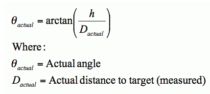
Remember, we are still looking for the variables that relate the laser dots distance from the center, to theta. Here’s the equation again:

We have two of those variables available to us, pfc was measured and theta can be worked out using inverse tan of h/d. If these two sets of numbers are plotted on a graph, the two constants rpc and ro can be obtained from the equation of the line.
Here are the two sets of numbers:
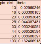
Now plot them on a graph, put a trendline throught the points and display the equation of the trendline:
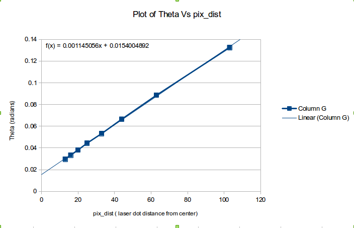
Plot of pix_dist vs theta
By comparing equations, rpc = 0.001145 and ro = 0.0154.
Now we can work out theta for a given pfc ( laser dots distance from center ). From here just fill into the equation D = h / tan(theta), job done.
Here is a video of it in action:
Feel free to ask any questions!

Pingback: 2D Room Mapping With a Laser and a Webcam
You can do rowsum (or colsum) to get close to region of max pixel. That can be fast.
If you find the region of maxness of the ifft2(fft2(image),fft2(dot,zeropad)) then you can fit a quadratic surface to it, find the analytic root, and go sub-pixel for your measurement.
Hi EngrStudent,
This is an interesting idea, but can you explain a little bit more about how it would work please?
It kind of looks like you convolving the image with an impulse (the zeropadded dot) by IFFTing the product of their FFTs, but presumably I’m missing something because I don’t think convolving the original image with an impulse would actually change it at all. Am I reading it wrong?
Ted
great project! i would like to ask you about accuracy vs distance. the lateral displacement of the laser dot is inversely proportional to the distance to the reflective surface. this is apparent when you demonstrate your calibration run. accuracy would therefore also keep reducing with distance. would that be correct? have you found a way around this?
Thats correct yeah. It’s caused by the fact that the camera lens is curved. You can account for this by finding two characteristics : the radians per pixel pitch and the radian offset of your webcam. I’ve outlined how to do that in this post, or you could check out Todd Danko’s post here: https://sites.google.com/site/todddanko/home/webcam_laser_ranger. This allows for linear measurements even though as you said, the lateral displacement of the dot is inversely proportional to the distance of the surface.
Dear sir! First of all, i wanna to say you thank about your too much precious and valuable work on 2D mapping using laser mouse. Dear sir, my boss has given me a task to work on robot project of 2D mapping of any place . i have searched many techniques for building 2D map but i found your work too much accurate. but sir i am unable to view full page. There are some errors occuring in the page https://shaneormonde.wordpress.com/2014/01/25/webcam-laser-rangefinder/ . Sir if you don,t mind. then you can send me full details or helping material on 2D mapping using laser mouse as a guidance. i will be very thankful to you if you help me in this problems. kindly send me the full details or any helping material on my email engr.adnan13@yahoo.com
Hi Adnan, there are no errors occuring on my end. It can be viewed in both chrome and firefox without any problems.
Pingback: Study Buddy - Research and Development | Digital Media
Pingback: using range-only sensors for mapping in SLAM | DL-UAT
Pingback: Laser Rangefinder Webcam DIY Python - HTML CODE
Pingback: How to make a 3 dimensional distance scanner using a webcam? | Siddharth Jha
Do you have it in C#? I’m a recently graduated student and we haven’t done C++ and VB
I don’t unfortunately! I write my Python very similar to C language. So it should be possible to port it over without too much trouble.
Shane
Okay i will try and do that thank you.
Hi,
this is really great project,
can you please explain about these values , i am not getting any idea.
rpc = 0.001145 and ro = 0.0154.
i just want to calculate distance between lens and object using webcam , kindly suggest..
Thanks
Hey Priyanka, I’ll try to explain this probably tomorrow. It is a little tricky to understand this stuff
Hi, can you please explain my points that i asked before and why h=5.33 is it in cm ?
Hi, the video is uploading now – in the next hour you can watch it at this link: https://youtu.be/qtI5SFyyB2A
So this method only uses half of the image. Why don’t you tilt the laser to fully use the image and get larger range?
hey chen, because i didn’t know I could do that. Interesting point though. Does this change the maths involved?
Hi, how do I generate this class : #include “stdafx.h”
Sorry, that class is okay the one I want to unde is this one: #include “LVServerDefs.h”
Hi! That’s a good job. but I have a question;
My boss has given me a task to work on mesaurement between two lines. Do you have any idea how can I solve this problem?
I mean I have lots of ropes and I should measurement distance between 2 ropes with camera and then the other two. please give me any idea.